| Features:
Display:
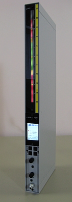
The L9100 includes a 100-segment bar display consisting of
rectangular high-intensity tricolour LED's digitally programmable
as either red, green or amber. The bar display also includes 3
digitally programmable marker LED's.
A
new 2.4" diagonal, Backlit Colour Graphical LCD Display is
provided for the main operating mode readout, and also for
programming. In addition to displaying the measured part
value in large characters, the operating mode screen also provides for
a user-programmed 17-character part description, 3
user-programmed 'LED' Limit annunciators, Mini-bargraphs to show
the current zero & gain settings, display of the current
Setup number (1-8), and a variety of other features described in
detail in the operating manual.
Ranges: A total of 100 Inch ranges are provided, from 1 Thou to 100 Thou; 100 Metric Ranges are
provided from 20 to 2000 microns, and 100 Degree Ranges are provided, from 0.1 to 10 degrees.
Security: When engaged, a
5-digit Primary Security Code prevents unauthorized access to the programming
menus; a Secondary Security Code when engaged, prevents access to both the Part
Selection and Automastering functions.
Programming Setups:
In one simple step, the operator may select from 1 to 8 available
part configurations. Each setup has independent calibration
settings, ranges, and limit and mastering setups which are stored in
the column. No re-mastering is required when changing between
setup fixtures. In programming the Setups, the unit provides the
capability of copying from one setup to another, to facilitate the
programming of Setups which may have only minor differences between
them. This feature can also be used to provide a 'Backup' of an
existing setup for security purposes.
Automastering:
Once Min and Max master values have been programmed, the operator needs only to
press the <Enter> button as prompted by the display readout. The column
will automatically calibrate itself. If an error occurs in this process (ie
incorrect masters etc.), then an error message will be displayed and the column
will maintain its original calibration settings. A master automaster pushbutton
connection (for multiple columns) is also available on the column rear.
Total Indicating Readout (TIR):
Functions available from the TIR programming menu include Max,
Min, Max-Min and ABS. When for example, Max-Min is selected,
the column will display the difference between the maximum and minimum
signals, and will hold that position on the display until the values
are exceeded, or a reset is performed. This feature is often used
when measuring a parameter such as 'out-of-round' , when a part is
rotated in a fixture. TIR may be set to ON either via the
programming menu, or an optional front-panel mounted switch with reset
pushbutton. TIR may also be reset via a remote pushbutton,
connected to the rear of the unit. The Auto-Reset feature, when
engaged, will trigger a TIR reset each time a new part is placed in the
gaging fixture; the reset is based on the display position as a
result of part replacment, and incorporates a programmable time delay.
Data Communication: The L9100 Column
Gages have a standard RS232 communications port for interface to another device.
The most common application of this is for the transfer and storage of data
readings to a computer. A 9-pin subminerature 'D' connector on the rear of the
column allows connection to a PC using a standard serial cable.
When a
reading is taken, the setup number, column station number, column number, and gaged reading
are sent to the serial port according to an established protocol. A connector
on the rear of the column provides the interface for connection to either a
'Read' button, or to relay contacts in an automated system. When the contacts
are closed, a reading is transmitted from the serial port.
When
multiple columns are used at a gaging station, they may be 'daisy-chained'
together for serial communications. Short jumper cables interconnect the
columns at the rear. The serial cable connects to only the first column in the
chain. When a reading is taken, all of the columns transmit their data, one
after another in sequence through the serial port, thereby requiring only one
cable from the column gaging station to the PC.
The
L9100 column includes a number of serial protocol options
which can be user-programmed to meet the requirements of most
commercially-available software.
Status
Outputs:
Status Outputs include HI, OK & Lo Limits, and Approach
Hi and Approach Lo. Outputs are normally +5V (or relay
energized) on reaching the programmed limit value. If desired
however, these can be programmed as inverted.
In the standard configuration, 3 hard-wired output connections are
available on the column rear for limit status, where the output is normally 0
volts, and goes to +5 volts when the status is reached. Three programmable
limit output types are available for these outputs.
Output type 1
provides the normal spec limits of HI, OK and LO through the three output lines.
Output type 2 provides Approach LO, OK, and Approach HI through the same three
output lines. Output type 3 provides Approach HI or LO, OK, and Spec Limit HI
or LO. These are all provided as standard on the L9100.
As an option
& special order, all 5 status outputs can be brought individually. These
include spec HI, Approach HI, OK, Approach LO, and Spec LO.
Relay
Outputs: Customers may optionally order L9100 Columns with relay outputs.
When relays are included, the status connectors on the rear of the column which
are normally used for the voltage outputs described above, are instead used for
the relay contact outputs. Relays are normally open/normally closed contact.
Contact ratings are 2 amps max @ 30Vdc or 0.6 amps max @ 120
Vac.
 |
| |


